Nortel-networks BCM50 User Manual Page 203
- Page / 280
- Table of contents
- BOOKMARKS
- BCM50 2.0 1
- Trademarks 2
- SOFTWARE LICENSE 3
- Task List 5
- 8 Task List 8
- Contents 9
- Appendix N 15
- 16 Contents 16
- Regulatory information 17
- EMI/EMC (FCC Part 15) 18
- Important safety instructions 19
- Use of a music source 20
- Enhanced 911 configuration 21
- Radio-frequency interference 21
- 22 Regulatory information 22
- Additional safety information 23
- 24 Regulatory information 24
- Chapter 1 25
- 26 Chapter 1 Getting started 26
- Symbols and text conventions 27
- Related publications 29
- How to get help 30
- Chapter 1 Getting started 31 31
- 32 Chapter 1 Getting started 32
- Chapter 2 33
- ports and connectors 35
- Media bay modules 40
- Trunk media bay modules 41
- Global Analog Trunk Module 42
- Station media bay modules 43
- 4x16 media bay module 44
- BCM50 hardware 48
- Patch panel 49
- Wall-mount bracket 49
- BCM50 components 50
- Power supply 51
- Uninterruptable power supply 51
- Hard disk 52
- Cooling fan 53
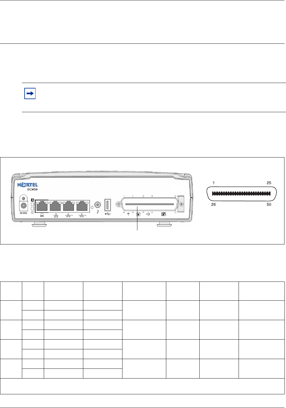
- RJ-21 telephony connector 54
- Field-replaceable units 55
- Telephones and adapters 56
- ABC DEF 57
- GHI JKL MNO 57
- PQRS TUV WXYZ 57
- Accessories 59
- Chapter 3 61
- LAN port LEDs 62
- Figure 30 MBM LEDs 66
- DTM LEDs 67
- BRIM LEDs 68
- Chapter 4 69
- (with integrated router) 70
- Chapter 5 73
- Chapter 6 77
- Digital loop 78
- Analog loop 78
- Basic hardware 79
- Optional equipment 79
- Other hardware and tools 79
- • punch-down tool 80
- Chapter 7 81
- Unpacking the main unit 82
- Slots Feet 85
- (optional) 90
- To install the WFC 90
- Chapter 8 93
- Unpacking the expansion unit 94
- To set GASM dip switches 96
- To set GATM dip switches 97
- To install an MBM 97
- Chapter 9 99
- Connecting the expansion unit 100
- To connect an expansion unit 101
- Connecting the power supply 102
- Figure 51 Connect a UPS 103
- NN40020-302 104
- Wiring warnings 105
- G4x16/G8x16 108
- G8x16 MBMs 109
- Music source specifications 111
- Figure 52 Music source jack 112
- Next step 114
- Chapter 10 115
- Installing IP phones 117
- Chapter 11 119
- Installing the ATA2 120
- To connect the ATA2 121
- Mounting the ATA2 121
- To mount the ATA2 on a wall 121
- Figure 57 ATA2 back view 122
- Mounting keyhole slots 122
- Configuring the ATA2 123
- Chapter 12 125
- Initial parameters overview 126
- Startup parameters overview 127
- Chapter 13 129
- To enter the keycodes 130
- To configure the IP address 131
- To configure the modem 131
- To select the region 132
- To initialize voice mail 132
- Chapter 14 135
- Prerequisites 136
- Accessing the BCM50 system 136
- To enter a keycode 137
- To configure IP Phones 141
- To configure SNMP settings 142
- To create user accounts 143
- Chapter 15 145
- Startup Profile requirements 146
- Configuring basic parameters 147
- Chapter 16 151
- To configure the MBM(s) 152
- Configuring modem settings 153
- Checking for software updates 153
- Configuring voice mail 153
- Customizing security policies 153
- Performing a backup 154
- Chapter 17 155
- Chapter 18 161
- To troubleshoot the main unit 162
- To test the expansion unit 162
- To test the MBM 163
- To test a station MBM 163
- To test a trunk MBM 163
- Reset to factory settings 165
- Activate the reset feature 166
- Table 32 Level 1 reset 168
- Table 33 Level 2 reset 168
- Chapter 19 169
- To shut down the system 170
- Chapter 20 171
- Removing the power supply 172
- Connect the new power supply 172
- Chapter 21 175
- Removing the main unit 176
- Installing the new main unit 177
- To connect the cables 178
- Chapter 22 179
- To remove the MBM 180
- To insert the new MBM 181
- Chapter 23 183
- Disconnecting the cables 184
- Removing the expansion unit 184
- Removing the MBM 186
- Chapter 24 189
- Special tools 190
- Opening the main unit case 190
- To open the main unit case 191
- To remove the hard disk 193
- To remove the fan 194
- Inserting the new component 195
- To insert the new hard disk 196
- Fan cable cutouts 197
- Fan cable clips 197
- To insert the new fan 198
- To insert the new router card 199
- Closing the main unit case 200
- Installing the main unit 201
- Connecting the cables 201
- Appendix A 203
- Appendix B 207
- Table 36 BRI line numbering 208
- Appendix C 209
- Table 37 LAN port wiring 210
- Appendix D 211
- Appendix E 213
- Appendix F 215
- Appendix G 217
- Appendix H 219
- Appendix I 221
- Appendix J 225
- Appendix K 229
- (Sheet 2 of 2) 232
- Appendix L 233
- Appendix M 237
- Digital interfaces 240
- Tones and cadences 241
- • Reorder on page 247 242
- Functionality Attribute 249
- Market profile 249
- Analog Trunk parameters 260
- GASM8 parameters 264
- GASI parameters 266
- Aspect Parameter 267
- Market Profile 267
- ATA2 parameters 268
- ATA2 DR7 270
- ISDN line services 271
- Analog trunk types: 273
- Trunk types Description 273
- Digital trunk types 273
- Numerics 275
- 280 Index 280
Related products and manuals for Phones Nortel-networks BCM50
 (90 pages)
(56 pages)
(62 pages)
(24 pages)
(34 pages)
(152 pages)
(42 pages)
(102 pages)
(16 pages)
(160 pages)
(14 pages)
(25 pages)
(129 pages)
(90 pages)
(56 pages)
(62 pages)
(24 pages)
(34 pages)
(152 pages)
(42 pages)
(102 pages)
(16 pages)
(160 pages)
(14 pages)
(25 pages)
(129 pages)
© 2020, manymanuals.com. All rights reserved. | 0.055 s |
 Manymanuals.com
 Manymanuals.de
 Manymanuals.fr
 Manymanuals.it
 Manymanuals.pl
 Manymanuals.cz
 Manymanuals.es
 Manymanuals-pt.com
Comments to this Manuals